What Steel Shop Drawings Are and Who Uses Them
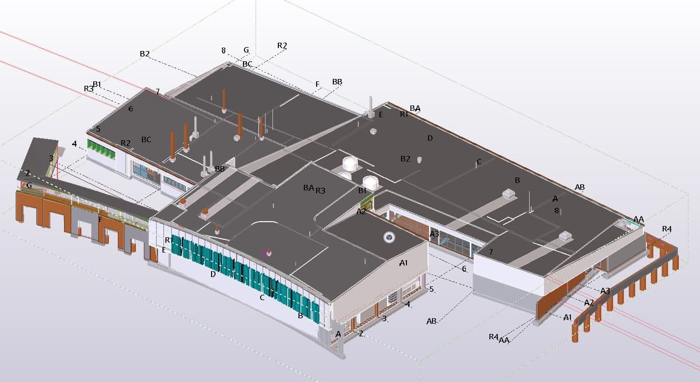
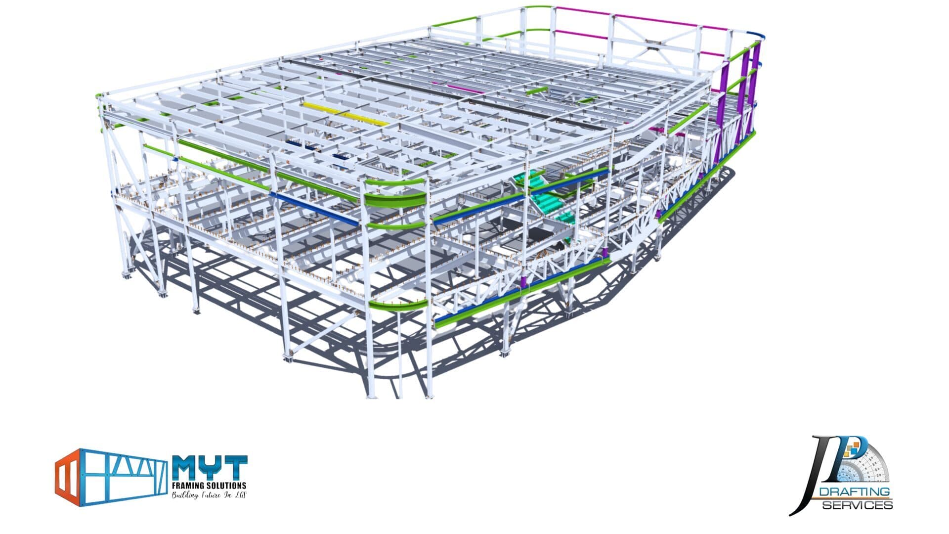
Steel shop drawings are the fabrication-level documents produced from a detailer's three dimensional model. Where an engineer's drawings describe how a structure behaves, steel shop drawings describe how each piece of it gets made. They are the only documents a boilermaker actually works from.
Four groups rely on the same package for different reasons. The workshop uses them to cut, drill and weld. The engineer reviews them to confirm the design intent survived translation. The site crew uses the erection plans to know what goes where. Procurement uses the material lists to buy steel and fasteners.
That shared dependency is why a weak package causes trouble in four directions at once. A dimension missing from a single part drawing does not just slow one operation, it stops a member reaching the paint line, which delays a load, which idles a crane.
The Two Types of Steel Shop Drawings: Assembly and Single Part
Every steel shop drawings package is built from two document types that serve different stages of fabrication.
Assembly drawings
An assembly drawing shows a complete shop-welded unit: the main member plus every cleat, stiffener, end plate and gusset welded to it before it leaves the workshop. It carries the assembly mark, the overall dimensions, the position of each attached component, weld symbols and sizes, and the finish specification.
This is the drawing a welder works from. It answers one question precisely: what does this finished piece look like when I am done with it.
Single part drawings
A single part drawing covers one individual component: a plate, a cleat, a length of beam. It gives the cut length, hole positions and diameters, bevels, cambers and grade. These feed the cutting and drilling operations that happen before anything is welded together.
In a well organised package the two are cross referenced. Standing at the assembly drawing you can identify every part mark it contains, and standing at a single part drawing you can see which assemblies consume it.
What Every Set of Steel Shop Drawings Must Show
Regardless of who produces them, a complete set of steel shop drawings carries the same core information. Use this as a checklist when reviewing an incoming package.
- Mark numbers that are unique, logical and consistent between drawings, lists and the physical hard stamp on the steel.
- Full dimensions with no reliance on scaling. If a dimension is not stated it does not exist.
- Hole information including diameter, position, and whether holes are punched, drilled or slotted.
- Weld symbols to AS/NZS 1554 specifying type, size, length and whether shop or site welded.
- Material grade and section designation for every component.
- Surface treatment covering blast standard, primer, galvanising or intumescent requirements.
- Revision block showing what changed, when, and against which engineering revision.
- Bolt specification including grade, diameter, length and whether snug tightened or fully tensioned.
How Steel Shop Drawings Drive CNC Fabrication
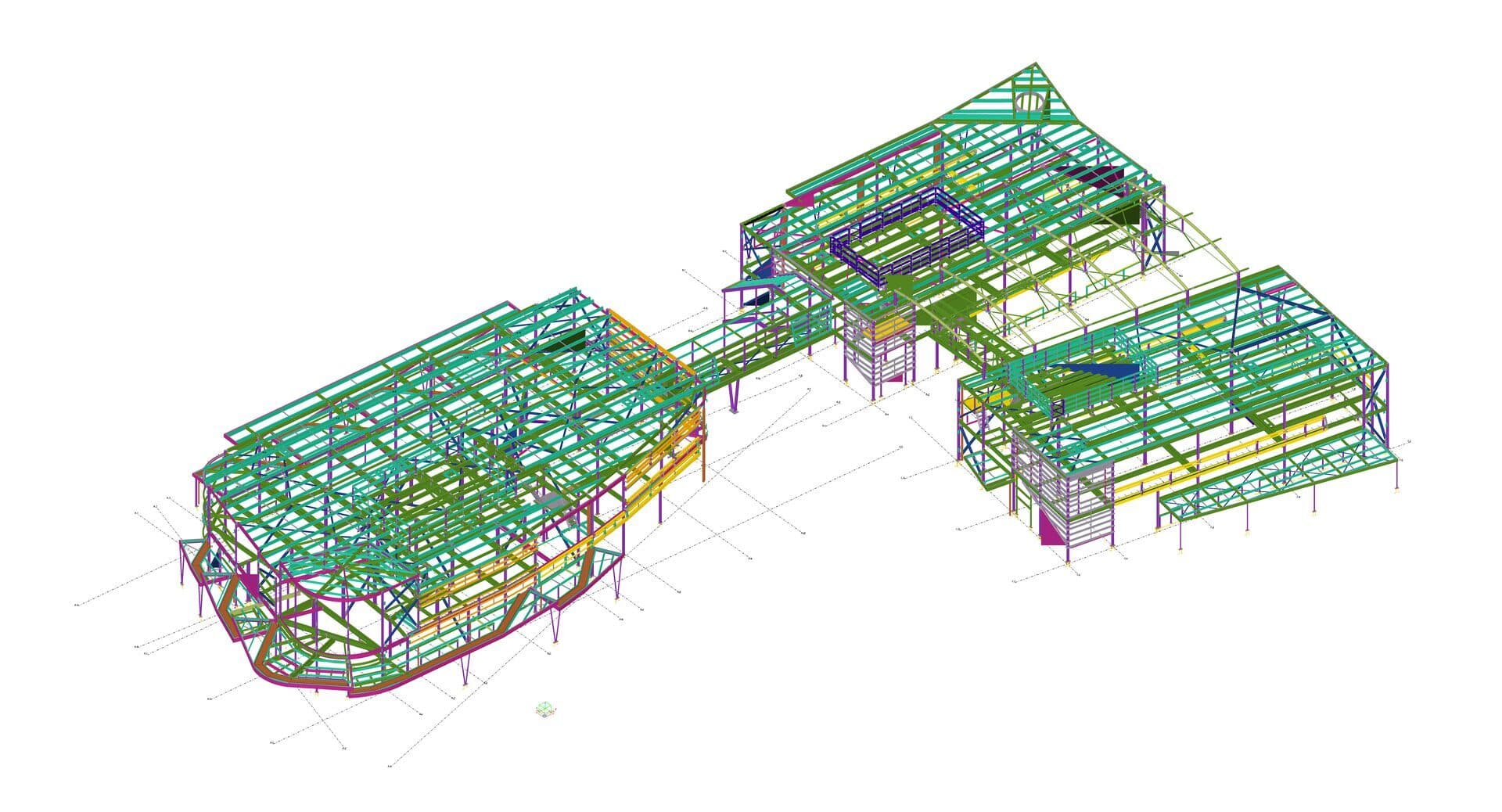
The most valuable output of modern detailing is not the drawing at all, it is the machine data extracted alongside it. When steel shop drawings come from a properly built model, the same model exports NC files that drive equipment directly.
- DSTV NC files feed beamlines for drilling, coping and marking without an operator entering a single dimension.
- DXF profiles drive plate processors, plasma tables and laser cutters.
- Hard stamp data lets the beamline mark part numbers directly onto steel, which removes a whole class of assembly errors.
The efficiency gain is significant, but so is the accuracy gain. Manual data entry introduces transcription errors at a predictable rate. Removing that step removes those errors entirely.
Steel Shop Drawings Approval and the Review Cycle
Steel shop drawings are almost always submitted for engineering review before fabrication begins. Understanding what that review is, and what it is not, prevents a common and expensive misunderstanding.
The engineer reviews the package to confirm it reflects the design intent. That review does not transfer responsibility for dimensional accuracy, fit or fabrication practicality to the engineer. Those remain with the detailer and fabricator. A stamped drawing with a wrong hole position is still a wrong hole position.
- 01Submission. The package is issued for review with a transmittal listing every drawing and its revision.
- 02Review. The engineer marks up comments, typically within one to two weeks depending on package size.
- 03Incorporation. The detailer resolves each comment and records how it was addressed.
- 04Resubmission or release. Depending on the significance of the comments the package either goes back for a second review or is released for construction.
The single biggest programme risk in this cycle is silence. A package sitting unreviewed for three weeks pushes fabrication three weeks later, and that delay is rarely recoverable once the workshop schedule has been filled with other work.
Revision Control for Steel Shop Drawings
Almost every expensive detailing failure we have investigated traces back to revision control rather than to a drawing error. The drawing was correct. It was simply not the drawing the workshop was holding.
Steel shop drawings move through several revisions before fabrication: an initial issue for review, one or two revisions incorporating engineering comments, and often further revisions as the design develops during construction. Each of those revisions has to reach the floor and, just as importantly, each superseded version has to leave it.
- Issue by transmittal, always. Every issue should list each drawing and its revision, so there is a record of exactly what was sent and when.
- Reference the engineering revision. A shop drawing revision block should state which structural drawing revision it was detailed against.
- Use clouds and revision triangles. A reviewer should be able to see what changed without comparing two full drawings side by side.
- Control printed copies. Uncontrolled paper on a workshop floor is the most common route to fabricating from a superseded drawing.
- Hold a single source of truth. One location where the current revision lives, rather than drawings distributed across individual inboxes.
Where fabrication has already started when a revision lands, the transmittal should say explicitly what is affected and whether work in progress must stop. Leaving that judgement to whoever opens the email is how partially fabricated assemblies end up scrapped.
Reading Steel Shop Drawings: Marks and Conventions
Mark numbering is the navigation system of a steel package. Conventions vary between workshops, but the logic is consistent.
- Assembly marks identify a complete welded unit, often prefixed by type, for example B for beams and C for columns.
- Part marks identify individual components within an assembly and are usually prefixed differently, commonly with p.
- Erection marks appear on marking plans and correspond to the assembly marks so the site crew can locate each piece.
- Quantity notation tells the workshop how many identical pieces to produce from one drawing.
Drawing conventions themselves follow Standards Australia guidance under AS 1100, which is what makes a package readable by any competent tradesperson rather than only by the office that produced it.
Steel Shop Drawings Errors That Reach the Workshop Floor
Some errors are caught in checking. These are the ones that survive to the floor, ranked by what they cost to recover.
- 01Holding down bolt setout errors. Discovered after the concrete has cured, which makes remediation slow, visible and expensive.
- 02Mark number duplication. Two different pieces sharing a mark means the wrong one gets shipped, and the error is only found at erection.
- 03Incorrect member length. Recoverable if too long, scrap if too short.
- 04Missing or wrong weld size. Under-welding is a structural defect. Over-welding is wasted labour and distortion.
- 05Wrong bolt grade or length. Stops erection until the correct fasteners are on site.
- 06Superseded revision in the workshop. A process failure rather than a drawing failure, and entirely preventable with disciplined transmittals.
Most of these are prevented by the same control: an independent checker who did not build the model. At JP Drafting Services every package is checked by a second detailer before issue. You can read more about how we produce structural steel detailing packages or about the software we model in.
Steel shop drawings FAQs
What is the difference between steel shop drawings and structural drawings?
Structural drawings are produced by the engineer and describe the design: member sizes, grid lines, loads and design actions. Steel shop drawings are produced by the detailer and describe fabrication: exact lengths, hole positions, weld sizes, mark numbers and finishes. One is a statement of what the structure must achieve, the other is a set of instructions for making the pieces that achieve it.
Who is responsible for approving steel shop drawings?
The structural engineer of record normally reviews and approves steel shop drawings for conformance with design intent. That approval does not transfer responsibility for dimensional accuracy or fabrication practicality, which stay with the detailer and fabricator. The allocation of responsibility should be stated explicitly in the contract rather than assumed.
How long does it take to produce steel shop drawings?
A small portal frame package can be issued within a week. A one hundred tonne commercial package typically takes three to five weeks including checking. Complexity matters more than tonnage: architecturally exposed steelwork with bespoke connections can take several times longer per tonne than repetitive industrial framing.
What software is used to create steel shop drawings?
Tekla Structures and Advance Steel dominate Australian steel detailing. Both build a three dimensional model first and extract drawings, NC data and material lists from it, so that a change to a member updates every document referencing it. AutoCAD is still used for two dimensional documentation and for conversion work.
Do steel shop drawings include connection design?
Not automatically. Connection design is an engineering activity that determines required capacities and is certified by an engineer. Detailing resolves that design into buildable geometry. Some detailers offer certified connection design as an additional service, but if it is not explicitly in scope you should assume connections will be detailed to a design supplied by others.